Volume relaxation
Introduction
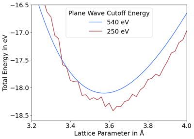
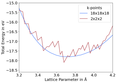
When relaxing the volume of cells, care must be taken. If too small an ENCUT or k-mesh are used, then discontinuities in energy vs. volume curves can be seen, cf. Fig. 1 and 2. This is due to an unconverged basis set being used. This creates unphysical forces, known as Pulay stress, that distort the cell structure away from equilibrium, decreasing the volume. This Pulay stress can be neglected in volume-conserving relaxations but becomes important in volume relaxations.


How to correct
The Pulay stress may be corrected in multiple ways. Generally, by calculating the relaxed structure with a larger basis set by increasing the ENCUT until convergence is reached:
- Set ENCUT to 1.3 × the default cutoff, or PREC=High in VASP.4.4. Note: this is the lower recommended limit.
- Re-run VASP with the default cutoff to obtain the final relaxed positions and cell parameters.
- Further increase the ENCUT and repeat Steps 1 and 2, until the structure no longer changes, i.e. is converged.
| Mind: This relaxation is done along all of the lattice vectors. If you want to relax only one and keep the others fixed, e.g. for the vacuum in a surface relaxation, then LATTICE_CONSTRAINTS may be used instead. This can constrain any of the three lattice vectors for orthorhombic cells, or specific rows and columns in the lattice matrix for non-orthorhombic cells. |
If volume relaxations are necessary, the following two procedures may be followed:
1. Volume relaxation
One way is to very accurately relax the structure in a series of calculations on one structure:
Step 1.
Relax from the starting structure (ISIF = 7; IBRION = 1, 2, or 3) with Gaussian or Methfessel-Paxton smearing (ISMEAR = 0 or 1). Note: other settings can be used for ISIF, e.g. 3, 6, or 8 but it is not recommended to relax more than one degree of freedom at a time. For instance,
ISMEAR = 0 ; SIGMA = 0.05 # change smearing to ISMEAR = 1 ; SIGMA = 0.2 for metals
ISIF = 7 ; IBRION = 2; NSW = 20
Step 2.
Copy the CONTCAR to POSCAR and relax the structure again.
ISMEAR = 0 ; SIGMA = 0.05 # change smearing to ISMEAR = 1 ; SIGMA = 0.2 for metals
ISIF = 7 ; IBRION = 2; NSW = 20
ISTART = 1 # this keeps that energy cut-off constant, while updating the plane wave basis for the new cell volume
Step 3.
Change the smearing method to the tetrahedron method (i.e. ISMEAR=-5) and perform a single point calculation, i.e. no relaxation of structure. These will give highly accurate energies.
ISMEAR = -5 # tetrahedron method
NSW = 0
(Optional)
The previous steps should yield good energies. If there are still problems, such as the energy vs. volume curve remaining jagged, a few more additional steps may be tried:
Step 4a.
Try further increasing the ENCUT. Alternatively, improve the FFT grid by setting PREC=Accurate.
Step 4b.
To avoid additional computational cost due to increased cutoff energy, the STRESS output in VASP may be corrected using PSTRESS. The Pulay stress is only weakly dependent on volume and ionic configuration; it is mainly determined by the composition and basis set. A good estimation for it is given in the output, e.g.:
external pressure = -100.29567 kB
The difference in this pressure (between the desired and a very large ENCUT) may then be used to correct for the Pulay stress. PSTRESS is set to this difference, then all volume relaxations will take PSTRESS into account. It is important keep in mind that PSTRESS should only be used if increasing the cutoff is not a viable option.
- Perform two single point calculations, one for the default and one for the higher ENCUT.
- Find the external pressure in the OUTCAR file, e.g.:
  external pressure =    -1311.32 kB

  external pressure =    -95.66 kB
- Find the difference between these external pressures. This is a good approximation of the Pulay stress. E.g.
difference in pressure = -1215.66 kB
- Set PSTRESS equal to this difference in the OUTCAR file, i.e.:
PSTRESS = -1215.66
This results in structures similar to the higher cutoff at the cost of the default cutoff. We reiterate that PSTRESS should only be used if the higher cutoff is not a viable option, as this only improves the structure and not the energy.
2. Equation of state fitting
An alternative way to avoid relaxing the volume is to relax the ionic positions and cell shape for a fixed set of volumes, i.e. multiple POSCAR files. These are then fitted to an equation of state, e.g. Murnaghan.[1] As the Pulay stress is almost isotropic, only a constant value is added to the diagonal elements of the stress tensor. Therefore, the relaxation for a fixed volume will yield highly accurate structures. This approach has the advantage of also providing the bulk modulus, and we have found it may be used safely with the default energy cutoff.
The procedure is similar to the previous section. In this case, one has to do the calculations for a set of fixed volumes. The following steps have to be done in these calculations:
Step 1.
Select one cell and relax it from the starting structure, keeping the volume fixed while the ionic positions and the cell shape are free to change (ISIF=4; ISMEAR=0 or 1). For instance,
ISMEAR = 0 ; SIGMA = 0.05 # change smearing to ISMEAR = 1 ; SIGMA = 0.2 for metals
ISIF = 4 ; IBRION = 2
Step 2.
Copy the CONTCAR to POSCAR and relax the structure again (if the initial cell shape was reasonable this step can be skipped if the cell shape is kept fixed, you never have run VASP twice).
Step 3.
Change the smearing method to the tetrahedron method (i.e. ISMEAR=-5) and perform a single point calculation, i.e. no relaxation of structure. These will give highly accurate energies.
Step 4.
Repeat Steps 1-3 for as many different volumes as desired and then fit the energy vs. volume curve to your chosen equation of state.
Possible issues and advice on how to address them
When producing energy vs. volume plots, improper settings may result in jagged curves, cf. Fig. 1 and 2. This is commonly due to two reasons:
- Basis set incompleteness
The basis set is discrete and incomplete, so when the volume changes, additional plane waves are added. That causes small discontinuous changes in the energy.
- Use a larger plane wave cutoff, cf. Fig. 1. This is usually the preferred and simplest solution.
- Use more k-points, cf. Fig. 2.[2]
- Discontinuity of FFT grids
Different precisions of the FFT grid defined by PREC may be used, e.g. Normal or Accurate.[3] This introduces small errors when the volume changes, as the FFT grids change discontinuously. In other words, at each volume a different FFT grid is used, causing the energy to jump discontinuously between different volumes. For more details on FFT grids, see [4].
- Use PREC=Accurate
- Increase the plane wave cutoff.
- Set your FFT grids manually, and choose the one that is used per default for the largest volume.
References
- ↑ Murnaghan Equation of State, www.wikipedia.org (2024)
- ↑ This solves the problem because the criterion for including a plane wave in the basis set is . This means at each k-point a different basis set is used, and additional plane waves are added at each k-point at different volumes. In turn, the energy vs. volume curve becomes smoother.
- ↑ For PREC=Accurate, the FFT grids are chosen such that is exactly evaluated. Whereas, for PREC=Normal the FFT grids are set to 3/4 of the value that is required for an exact evaluation of .
- ↑ Introduction to ab-initio simulation in VASP
