Category:Transition states: Difference between revisions
No edit summary |
|||
| (20 intermediate revisions by the same user not shown) | |||
| Line 1: | Line 1: | ||
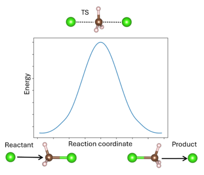
A '''transition state''' (TS) in chemistry refers to a high-energy, short-lived configuration that occurs during a chemical reaction as reactants transform into products{{Cite|tst:web}}. At this point, the reaction's progress is maximized. In other words, the transition state is a metastable structure that corresponds to a saddle point on the high-dimensional potential surface. Identifying the transition state is essential for understanding reaction mechanisms, energy barriers, and reaction rates. There are various methods available to pinpoint transition states in VASP. | [[File:Transition_state_pathway.png|400px|thumb|right|Reaction profile for the substitution reaction of chloromethane by chloride. This is a symmetric reaction, where the products and reactants are identical. The maximum of the reaction profile is the transition state (TS). The arrows indicate the direction of motion, showing the attack of the chloromethane by one chloride and then the ejection by the new chloride.]] | ||
A '''transition state''' (TS) in chemistry refers to a high-energy, short-lived configuration that occurs during a chemical reaction as reactants transform into products{{Cite|tst:web}}. At this point, the reaction's progress is maximized. In other words, the transition state is a metastable structure that corresponds to a saddle point on the high-dimensional potential surface{{Cite|hratchian:schlegel:2005}}. Identifying the transition state is essential for understanding reaction mechanisms, energy barriers, and reaction rates. There are various methods available to pinpoint transition states in VASP. | |||
<div style="clear:both;"></div> | |||
= Static methods = | |||
There are three methods implemented in VASP for finding transition states (TS) using the static, or harmonic, approach: the improved dimer method (IDM), nudged elastic band (NEB), and following the intrinsic reaction coordinate (IRC). IDM takes a guess structure for the TS and then relaxes it along a trial unstable vibrational mode to a first-order saddle point, i.e. the TS. NEB takes the reactant and product structures and interpolates structures between the two to model the reaction pathway. IRC starts at the TS and follows the TS' unstable vibrational mode to reactant and product. | |||
== Improved dimer method == | == Improved dimer method == | ||
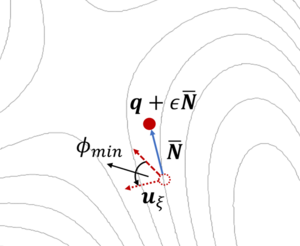
[[File:idm_single_image.png|300px|thumb|right|A dimer consisting of two points on the potential energy surface (PES) is rotated to find the lowest curvature. The structure is updated and then a new dimer is defined. The IDM converges towards the desired saddle point, i.e. the TS. | |||
The potential energy surface (PES) is described by a series of images (blue) connected by springs (green arrows). The initial (reactant) and final (product) states are shown in black and remain fixed. The transition state (TS) is the maximum of the PES (red).]] | |||
The dimer method{{Cite|henkelman:jpc:1999}} is a technique for determining activated transitions without knowledge of the final state. Beginning with a trial transition state (TS) structure, a relaxed TS is obtained. In VASP, the improved dimer method (IDM) by Heyden et al. is implemented. The modification reduces the number of gradient calculations per cycle, improving algorithm performance. A detailed presentation of the method can be found in their paper{{Cite|heyden:jpc:2005}}. The main tag is {{TAG|IBRION}}=44. | The dimer method{{Cite|henkelman:jpc:1999}} is a technique for determining activated transitions without knowledge of the final state. Beginning with a trial transition state (TS) structure, a relaxed TS is obtained. In VASP, the improved dimer method (IDM) by Heyden et al. is implemented. The modification reduces the number of gradient calculations per cycle, improving algorithm performance. A detailed presentation of the method can be found in their paper{{Cite|heyden:jpc:2005}}. The main tag is {{TAG|IBRION}}=44. | ||
Follow the how-to in order to learn [[Improved dimer method|how to perform an IDM calculation]]. | Follow the how-to in order to learn [[Improved dimer method|how to perform an IDM calculation]]. | ||
<div style="clear:both;"></div> | |||
== Nudged elastic bands == | == Nudged elastic bands == | ||
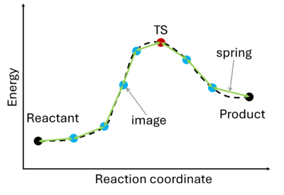
[[File:NEB.png|400px|thumb|right|The potential energy surface (PES) is described by a series of images (blue) connected by springs (green arrows). The initial (reactant) and final (product) states are shown in black and remain fixed. The TS is the maximum of the PES (red).]] | |||
The nudged elastic band (NEB) method{{cite|mills:surf-sci:1995}}{{cite|jonsson:book:1998}} involves the creation of an initial path connecting the system's initial and final states, utilizing a set of intermediate configurations ({{TAG|IMAGES}}). Hence, as a prerequisite, the initial and final state (e.g., reactant and product) must be known. The ''images'' are interconnected by springs ({{TAG|SPRING}}), forming a flexible ''band''. Through iterative adjustments (''nudging''), the positions of the images along the band are modified, minimizing energy until a minimum energy pathway, referred to as the ''nudged elastic band'', is attained. | The nudged elastic band (NEB) method{{cite|mills:surf-sci:1995}}{{cite|jonsson:book:1998}} involves the creation of an initial path connecting the system's initial and final states, utilizing a set of intermediate configurations ({{TAG|IMAGES}}). Hence, as a prerequisite, the initial and final state (e.g., reactant and product) must be known. The ''images'' are interconnected by springs ({{TAG|SPRING}}), forming a flexible ''band''. Through iterative adjustments (''nudging''), the positions of the images along the band are modified, minimizing energy until a minimum energy pathway, referred to as the ''nudged elastic band'', is attained. | ||
Learn [[Nudged elastic bands|how to perform an NEB calculation]]. | Learn [[Nudged elastic bands|how to perform an NEB calculation]]. | ||
<div style="clear:both;"></div> | |||
== Intrinsic reaction coordinate == | == Intrinsic reaction coordinate == | ||
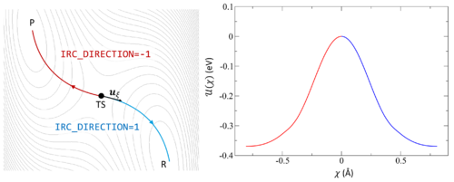
[[File:IRC.png|500px|thumb|right|The potential energy surface (PES) is shown as a contour plot. The IRC begins at TS and follows the associated imaginary frequency <math>u_{\xi}</math> forwards to the product P (blue) or backwards to the reactant R (red). The energy <math>U(\chi)</math> is plotted against the reaction coordinate <math>\chi</math> to illustrate the energy change as the PES is explored. | |||
described by a series of images (blue) connected by springs (green arrows). The initial (reactant) and final (product) states are shown in black and remain fixed. The transition state (TS) is the maximum of the PES (red).]] | |||
Following the intrinsic reaction coordinate (IRC) implies following the steepest descent path from the transition state to reactants and products. The IRC method employs a classical trajectory integration method with fixed velocity, i.e., the damped-velocity Verlet algorithm, incorporating an adaptive time step such that the dynamic reaction pathway resembles the IRC. Hence, as a prerequisite, the transition state must be known. The main tag is {{TAG|IBRION}}=40. | Following the intrinsic reaction coordinate (IRC) implies following the steepest descent path from the transition state to reactants and products. The IRC method employs a classical trajectory integration method with fixed velocity, i.e., the damped-velocity Verlet algorithm, incorporating an adaptive time step such that the dynamic reaction pathway resembles the IRC. Hence, as a prerequisite, the transition state must be known. The main tag is {{TAG|IBRION}}=40. | ||
Learn [[IRC calculations|how to perform an IRC calculation]]. | Learn [[IRC calculations|how to perform an IRC calculation]]. | ||
<div style="clear:both;"></div> | |||
= Dynamic methods = | |||
== References == | == References == | ||
[[Category:VASP|Transition States]][[Category:Ionic minimization]] | [[Category:VASP|Transition States]][[Category:Ionic minimization]] | ||
Latest revision as of 12:02, 18 October 2024

A transition state (TS) in chemistry refers to a high-energy, short-lived configuration that occurs during a chemical reaction as reactants transform into products[1]. At this point, the reaction's progress is maximized. In other words, the transition state is a metastable structure that corresponds to a saddle point on the high-dimensional potential surface[2]. Identifying the transition state is essential for understanding reaction mechanisms, energy barriers, and reaction rates. There are various methods available to pinpoint transition states in VASP.
Static methods
There are three methods implemented in VASP for finding transition states (TS) using the static, or harmonic, approach: the improved dimer method (IDM), nudged elastic band (NEB), and following the intrinsic reaction coordinate (IRC). IDM takes a guess structure for the TS and then relaxes it along a trial unstable vibrational mode to a first-order saddle point, i.e. the TS. NEB takes the reactant and product structures and interpolates structures between the two to model the reaction pathway. IRC starts at the TS and follows the TS' unstable vibrational mode to reactant and product.
Improved dimer method

The dimer method[3] is a technique for determining activated transitions without knowledge of the final state. Beginning with a trial transition state (TS) structure, a relaxed TS is obtained. In VASP, the improved dimer method (IDM) by Heyden et al. is implemented. The modification reduces the number of gradient calculations per cycle, improving algorithm performance. A detailed presentation of the method can be found in their paper[4]. The main tag is IBRION=44.
Follow the how-to in order to learn how to perform an IDM calculation.
Nudged elastic bands

The nudged elastic band (NEB) method[5][6] involves the creation of an initial path connecting the system's initial and final states, utilizing a set of intermediate configurations (IMAGES). Hence, as a prerequisite, the initial and final state (e.g., reactant and product) must be known. The images are interconnected by springs (SPRING), forming a flexible band. Through iterative adjustments (nudging), the positions of the images along the band are modified, minimizing energy until a minimum energy pathway, referred to as the nudged elastic band, is attained.
Learn how to perform an NEB calculation.
Intrinsic reaction coordinate

Following the intrinsic reaction coordinate (IRC) implies following the steepest descent path from the transition state to reactants and products. The IRC method employs a classical trajectory integration method with fixed velocity, i.e., the damped-velocity Verlet algorithm, incorporating an adaptive time step such that the dynamic reaction pathway resembles the IRC. Hence, as a prerequisite, the transition state must be known. The main tag is IBRION=40.
Learn how to perform an IRC calculation.
Dynamic methods
References
- ↑ Transition state theory, www.wikipedia.org (2024)
- ↑ H. Hratchian, H. Schlegel, Theory and Application of Computational Chemistry, Chapter 10 - Finding minima, transition states, and following reaction pathways on ab initio potential energy surfaces (2005), p. 195-249
- ↑ G. Henkelman and H. Jónsson, A dimer method for finding saddle points on high dimensional potential surfaces using only first derivatives, J. Chem. Phys. 111, 7010–7022 (1999).
- ↑ A. Heyden, A. T. Bell, and F. J. Keil, Efficient methods for finding transition states in chemical reactions: Comparison of improved dimer method and partitioned rational function optimization method, J. Chem. Phys. 123, 224101 (2005).
- ↑ G. Mills, H. Jonsson and G. K. Schenter, Reversible work transition state theory: application to dissociative adsorption of hydrogen, Surf. Sci., 324, 305 (1995).
- ↑ H. Jonsson, G. Mills and K. W. Jacobsen, Nudged Elastic Band Method for Finding Minimum Energy Paths of Transitions, in Classical and Quantum Dynamics in Condensed Phase Simulations, ed. B. J. Berne, G. Ciccotti and D. F. Coker (World Scientific, 1998).
Pages in category "Transition states"
The following 17 pages are in this category, out of 17 total.
